 The sealing in pinch valves is achieved throttling the flexible tube of the valve named elastic sleeve
which is the only part in contact with the medium.
The sealing in pinch valves is achieved throttling the flexible tube of the valve named elastic sleeve
which is the only part in contact with the medium.
Pinch valves are suitable for handling slurries and solids in suspension, avoiding contact with the
valve mechanism and any contamination towards or from the environment.
Generally, the pinch valve is limited to work at low pressures.
Pinch valves can be mechanically or pressure actuated. In mechanically actuated valves, as shown in the above picture,
especially when they are handing abrasive fluids, it is advised to close tightly the valve to prevent erosion of
the flexible tube by the effect of leakage flow.
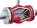 In pressure actuated pinch valves, as in the valve shown in the picture on the right,
the pressure is uniformly distributed over the external side of the flexible tub.
In pressure actuated pinch valves, as in the valve shown in the picture on the right,
the pressure is uniformly distributed over the external side of the flexible tub.
As advantage over the mechanically actuated valves, the pass section is always circular and then bigger particles
can go through.
But pressure actuated pinch valves can not be 100% closed and can not be manually controlled since there is
a dependency on the flow pressure, this can be resolve with a pressure regulator.
The flexible tube is made of elastomer, usually reinforced. Material selection should be done according
to a corrosion-strength commitment since the elastomer strength properties can be reduced by the attack of
the corrosive fluid.
Fatigue limit of the material must fit on-off valve cycling.
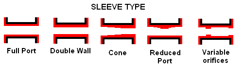
Sleeve Type:
-Full port: the sleeve diameter remains constant from inlet to outlet port.
-Double Wall: This wall gives more protection at cost effective and simple design for highly abrasive applications.
-Cone: design for control applications. By reducing the center section of the valve sleeve, it is possible to achive the required flow coefficient (Cv, Kv) of the valve.
-Reduced Port: as cone sleeve, the flow coefficient of the valve fits control application.
-Variable orifices: These orifices are designed for high-turndown control application. They also help avoid cavitation.
General features and ranges for Pinch Valves
|
Diameter ranges:
From 15mm to 1000mm.
Connection to the pipe:
Bead end, Flange, Screwed, Slip-on, Socket.
Sleeve material:
Chlorobutyl (CIIR), EPDM, Hypalon® (CSM), Natural rubber (NR), Neoprene (CR), Nitrile (NBR), Polyurethane (PU),
SBRT, Viton (FPM)
Temperature range:
From -50ºc up to +160ºC - (Depending on material).
Pressure range:
From -1 up to 100 bar - (Depending on material).
Fluid Velocity limitation:
Typical applications:
|